


 Print Article
 Raspberry Pi - Stepper Motor Control & Breakout Board


Overview
The kit includes:
- 1 @ printed circuit board
- 1 @ ULN2803 8 Channel Darlington Driver IC (Adafruit)
- 1 @ 18 pin DIP socket (Amazon)
- 8 @ green LEDs
- 1 @ Jumper and Jumper header
- 1 @ resistor array/network
- 1 @ capacitor
- 1 @ 26 pin PCB mount female header (not pictured)
- 1 @ peel-and-stick on rubber bumper (not pictured)
- 1 @ 28BYJ-48 5 VDC stepper motor (Amazon | Adafruit)
It is available now on eBay. << Click here to see John Jay's eBay listings >>
Assembly
<< http://mypishop.com/Stepper.html >>
Shopping List
- 1 @ Raspberry Pi (see this page for more Raspberry Pi related supplies)
- 1 @ John Jay's Stepper Motor Breakout Board (kit) (includes stepper motor)
Logic
 The stepper motor is controlled by pulsing the GPIO pins from LOW to HIGH states in a sequence that causes the motor to spin. Each time a GPIO pin state is HIGH an electromagnet is engaged inside the stepper motor to cause a rotational force on the center rotor. With the proper sequence and timing you achieve motor rotation.
Here is a fantastic article with photos and illustrations to help learn more about stepper motors and stepping techniquest:
http://www.lirtex.com/robotics/stepper-motor-controller-circuit/
Photos
Below are photos of the assembled board and attached stepper motor.
;)
;)
;)
;)
;)
Stepper Motor Ports
This breakout board includes two ports for controlling two separate stepper motors.
;)
You can purchase an additional stepper motor to use on the second port here:
GPIO Wiring Diagram
The two stepper motor controllers are mapped to GPIO pins on the Raspberry Pi's P1 header as depicted in the diagram below. The GPIO numbering in the diagrams below is based on the WiringPi / Pi4J numbering scheme. See below for a mapping chart for other numbering schemes.
- GPIO Pins 0 to 3 are mapped to the X1 motor controller port (LEFT).
- GPIO Pins 4 to 7 are mapped to the X2 motor controller port (RIGHT).
;)
GPIO Pin Cross-Reference Chart
Below is a cross reference chart to better help define the GPIO pin numbers used under the various pin numbering schemes.
;)
JP1 Jumper Information
A jumper is provided on the board to supply 5 VDC to the stepper motors directly from the 5 VDC output from the Raspberry Pi. If you would prefer to provide 5 VDC from an external power supply, please remove the jumper from JP1 and connect your power source to JP1 pins 2 and 3. See the diagrams below.
;)
Make sure that you place the jumper between pins 1 and 2.
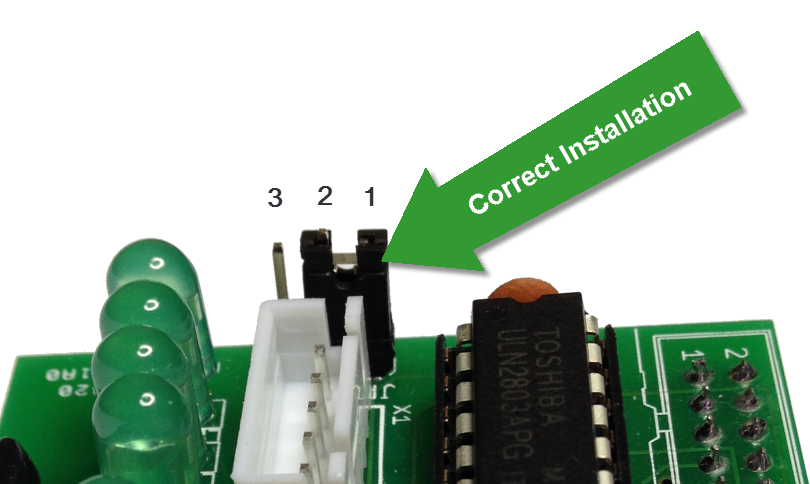
ATTENTION !
Never attach JP1 pins 1 and 3 together as this will cause a direct short on the 5 VDC power line from the Raspberry Pi. This would likely render the Pi defective.
Java Sample Program using Pi4J to Control Stepper Motor
Below is a sample Java program for controlling the stepper motor. The Pi4J project now includes a new stepper motor interface and component implementation for GPIO based stepper motors. This makes it really simple to control a stepper motor from Java. (Note that the stepper motor implementation is available in 0.0.5 and later versions of Pi4J.)
The source for this example is provided with the Pi4J installation package and can also be found on Github:
Final Thoughts
This was my first time working with a stepper motor and having this kit certainly made it much easier to understand and get started. For me the timing was the trickiest thing to get right. Fortunately with a little trial and error I was able to get it working. Here is a quick video demonstrating the final working project.
Happy New Year!
Reader Comments (14)
Hi Robert,
I have been trying out your pi4j library together with the evealpha board. I think pi4j is great, but would like to let you know of a problem I'm having with the SPI wrapper. In the wiringPiSPIDataRW() JNI wrappper, the String data parameter is used for both transmitted data as well as received data. From the code below (which I copied from your github project), it looks like the received data (should be in datachararr) is not being copied back into the Java data string. I can confirm this behaviour on my program which only ever receives the same data that is being transmitted.
Thanks again for a great product.
Franz
/*
* Class: com_pi4j_wiringpi_Spi
* Method: wiringPiSPIDataRW
* Signature: (ILjava/lang/String;I)I
*/
JNIEXPORT jint JNICALL Java_com_pi4j_wiringpi_Spi_wiringPiSPIDataRW
(JNIEnv *env, jclass class, jint channel, jstring data, jint length)
{
char datachararr[2048];
int len = (*env)->GetStringLength(env, data);
(*env)->GetStringUTFRegion(env, data, 0, len, datachararr);
return wiringPiSPIDataRW(channel, (unsigned char *)datachararr, length);
}
@Franz,
Thanks for posting this issue and I agree that it looks like a defect.
I have added it to the issues list on Pi4J.
https://github.com/Pi4J/pi4j/issues/28
Please register on this ticket to be notified of updates.
I am looking into the issue this evening.
Thanks, Robert
Hello Robert!
Thanks for this great project!
I think I made a mistake, in which you can help me.
- I soldered the whole thing up
- plugged in the motor
- compiled and run your example
Only LED1 lights up strongly and LED3 weak.
When I unplugg the motor only LED1 lights up.
Please help me. :)
Aww yes! I just successfully got all this going on my pi.
@meep
Glad to hear it! Thanks for posting your success.
Thanks, Robert
Hi,
I have been trying to wire up everything, but haven't got circuit board,
Is there better image of circuit board, or Can I connect everything without board? Any help is appreciated!
Thank you.
Look forward to hear from you guys.
I have got http://img.dxcdn.com/productimages/sku_140716_1.jpg prototype printed board though cannot see images clearly from this post how to wire everything... if you can, please advise any links that has step by step guide?!
thanks
Thanks for this prof. Demo.
Consider updating your links to ebay. The link now redirects to the search for the product where there are many similair-looking boards.
i installed everything as per the instructions... wiringpi... j4pi... i can run the script and i see the echos in the console, but i get no response from my stepper control board... no lights or motor movement.
is the pi2 different? do we need a different install to make this work on a pi2?
Uuu, really nice explanation. Thx.
Thanks for this great summary - use this template to control a chicken coop door (see author URL, page in German). There is just one thing which makes me curious: When I compile the code in BlueJ the timespan one motor runs seems to be correct. However, when I execute the same code directly in the command promt the time span is aprox. 20% shorter. Why?
For instance, the following code will produce 87 seconds of motor rotation in BlueJ but only ~ 60 Seconds in the command promt. (using double_step_sequence, Stepinterval of 2)
motor.reverse (87000);
Hey,
it seams to be a great product, but how can I connect the stepper motor to the PI model 3+ ?
Thanks
Katrin
Hi Robert,
Where in the code do you make the relationship with 00 01 02 03 to the GPIO pins from the Pi?
Thanks, Karel