


Raspberry Pi - RS232 Serial Interface Options (Revisit)


In the previous article Raspberry Pi - Installing a RS232 Serial Port we discussed how to install a RS232 port on the Raspberry Pi. This is a follow up article to suggest a few alternative interface options as the XBit RS232 level-shifter board has been unavailable (sold out) for while now.
There are two primary RS232 interface options you can choose from for serial connectivity:
Once you have a serial interface connected you can use the serial port for
(Click one of the above options to jump to that part of the article.)
Shopping List
The following items are included in this article:
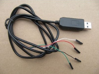
- PL2303HX USB to TTL to UART RS232 COM Cable module Converter
- MAX232 RS232 to TTL Converter Adapter Board
- 40pcs Female to Female 2.54mm 0.1 in Jumper Wires F/F
- Jumper Wires Premium 6" F/F Pack of 10
Serial Communication via USB
 If you are just looking to communicate to your Raspberry Pi via its serial UART, then you may prefer a USB interface. Most recent models of computers and laptops do not have the traditional RS232 DB9 port anymore, so connecting using a USB port may be preferred.
The following adapter is only $5.47 USD and it provides a USB to serial converter chip:
This adapter is based on the Prolific PL2303HX chipset. To use this USB to serial interface you will have to install a USB serial port driver on your host operating system. Many operating systems already include support for theserolific drivers. But in case you need it, the drivers can be found here: http://prolificusa.com/portfolio/pl-2303hx-usb-to-serial-bridge-controller/
Below is a wiring diagram illustrating how to connect the USB to serial interface:
;)
Photos of the connected USB to Serial interface (click to enlarge):
;)
;)
NOTE: Please secure the RED lead from the USB adapter so that it does not come into contact with any of the other pins or components on the Raspberry Pi. This RED pin carries +5VDC and could damage the Pi if it makes contact.
Now that you have the serial interface connected, you can skip down to the Serial Console section to test the interface.
Serial Communication via DB9 (Level Shifter)
;)
For certain applications and especially project involving interfacing with other hardware devices a standard RS232 serial device with a DB9 connector is preferred. A standard serial port such as this does not require any drivers. RS232 serial communication is standardized at the hardware layer. RS232 communication can also achieve longer distance runs (maximum distance depends on baud rate).
The following interface adapter is available for $9.99 USD:
In addition to the adapter, you will need at least 4 female to female 2.54mm .1 in jumper wires.
Here are a couple of purchase options:
Why is special circuitry (level shifter) needed for RS232 serial communication?
So .. what a level shifter and why is it needed you ask. A level shifter is a circuit that can take the low voltage (±3.3VDC) TTL signals for serial transmit (TX) and receive (RX) from the UART on the Pi and shift them to ±5VDC the voltage signals required for RS232 standard communication. Want to know more? Click here.
Below is a wiring diagram illustrating how to connect the level shifter serial interface:
;)
Now that you have the serial interface connected, you can skip down to the Serial Console section to test the interface.
(Use a straight-thru cable for connecting to a computer.)
Serial Console
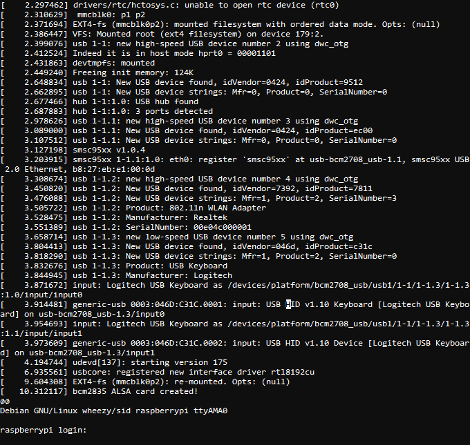
The Debian/Raspbian distribution images include support out-of-the-box for accessing the shell console via the hardware serial port. This can be extremely convenient if you need to access your Raspberry Pi when it is not connected to a monitor and network remote access is not available.
Open a terminal emulation software such as Hyperterminal, Procom Plus, or Indigo Terminal Emulator and connect to the serial port using settings "115200, N, 8, 1". You may need to press the enter key a time or two to see the prompt. Authenticate using your credentials and you are good to go.
Here is a screenshot of the terminal displaying the boot up information and then prompting for a login:
Software use of the Serial Port
If you intend to use the serial port for a software application running on the Raspberry Pi, there is a bit of configuration required to disable the console from using this port. By default, the serial port is configured as a console port for interacting with the Linux OS shell. The following steps will guide you through disabling the port from console access.
First, lets make of backup of the two files that we intend to modify.
sudo cp /boot/cmdline.txt /boot/cmdline.bak
sudo cp /etc/inittab /etc/inittab.bak
Next, we need to remove the "console=ttyAMA0,115200" and "kgdboc=ttyAMA0,115200" configuration parameters from the "/boot/cmdline.txt" configuration file.
To edit the file use this command:
sudo nano /boot/cmdline.txt
The file probably contains this default configuration line:
dwc_otg.lpm_enable=0 console=ttyAMA0,115200 kgdboc=ttyAMA0,115200
console=tty1 root=/dev/mmcblk0p2 rootfstype=ext4 elevator=deadline rootwait
After removing the two configuration parameters, it will look similar to this:
dwc_otg.lpm_enable=0 console=tty1 root=/dev/mmcblk0p2 rootfstype=ext4
elevator=deadline rootwait
The last step is to edit the "/etc/inittab" file and comment out the use of the "ttyAMA0" serial port. To edit the file use this command:
sudo nano /etc/inittab
Now towards the bottom of the file, look for a configuration line that includes the "ttyAMA0" port address.
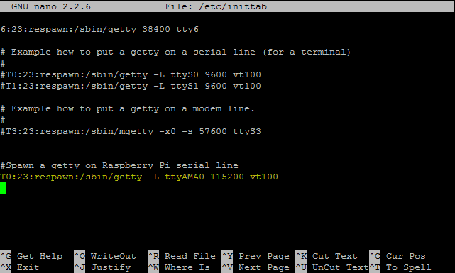
Place a pound sign ("#") in front of the line to comment it out. With a pound sign ("#") at the beginning of the line, Linux will ignore this configuration line.
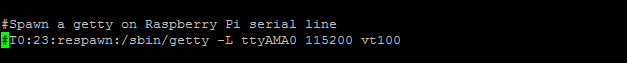
Save the "/etc/inittab" file and then issue this command to reboot the Raspberry Pi:
sudo reboot
Now you are ready to use the serial port with a software application and the operating system won't interfere with the port. Use the device address "ttyAMA0" in your application to access this serial port.
If are interested in using the serial port with Java programming, please see this page: http://pi4j.com/example/serial.html
 Robert Savage
I have updated the wiring diagram and photos for the USB TTL adapter approach to remove the 5VDC RED pin connection. It was technically working, but I felt it was safer to eliminate this connection to prevent current from being sourced from the USB connection/adapter back into the Raspberry Pi.
Reader Comments (36)
Thanks for giving the detail information about how to install a RS232 port on the Raspberry Pi.This will help us to known more about this device.Fantastic Blog, it’s so helpful to me, and your blog is very good,I’ve learned a lot from your blog.
I'm architecting a system using a Raspberry Pi that will require the use of two RS232 serial streams as inputs. I can use external logic to mux the two RS232 input lines to select just one at a time if needed... but is there an easier way? Has anyone tried using one of the GPIO lines on RP to input an RS232 stream?
THANKS!
@Dave,
No I have not seen anyone using the GPIO and software bitbanging to facilitate an additional serial input. I have used an USB to serial adapter with the Pi. Other have reported trouble using USB to serial adapters, but I don't recall the details.
I'm hoping for a bit of advice...
I want to use the serial out to communicate with a PLC from the RaspPi, and occasionally I'll jack-in a laptop to reprogram the PLC. My current setup allows me a "serial pass-through", where I use USB->serial on the laptop, and forward the laptop signals through the computer to the PLC. This means I'd need the RaspPi to have 2 serial ports. Do you know of a standard way of doing this?
@J Knight,
You could use a USB to serial adapter on the Raspberry Pi. I have tested in the past with a USB to RS232/DB9 adapter connected to one of the USB ports on the Raspberry Pi. The one I used had an FDTI chipset and the Raspberry Pi automatically loaded a driver for me.
Thanks, Robert
WARNING!
I bought a cheap Chinese MAX3232 RS232 Serial Port To TTL Converter Module DB9 Connector 3.3-5V Input on Ebay http://www.ebay.nl/itm/170883124088?ssPageName=STRK:MEWNX:IT&_trksid=p3984.m1497.l2649. This converter has a female DB9 connector so I bought a mini gender changer as wel.
It did not work. I found that the Rx and Tx are reversed in this module. I had to modify the genderchanger (don't ask how) to solve this problem. Now it's working fine...
I have to correct myself. Since the DB9 connector is female, Rx is on pin3 which is correct. The thing is however that you would expect a male connector where the RS232 signal comes out of a computer. Now that is is a female you can't connect a CM11 computer interface to it. The use if a genderchanger won't help unless you reverse Tx and Rx. This means not between the raspberry and the convertor but between the DB9 connectors. I opened the genderchanger, removed the unused pins, cross connected the Tx and Rx and managed to put it together again. Now my homeautomation works fine.
Hope this helps someone....
I'm not sure about the wiring diagram in the first image, according to a discussion on the amazon page you linked to, the red wire is 5V output *from* the USB, and so shouldn't be connected to the RasPi's header - just connect the GND, TX and RX wires.
However the diagram for the second adapter is correct as it does need to take power from the Pi.
Thanks for this. I wrote an RF application using the serial port nearly a year ago, and had to upgrade recently to a new version of Wheezy to get some new drivers for WiFi. In my original development I had omitted the above steps from my documentation and had been pulling my hair out for a day until I saw this. If you don't do the above It makes a serial dialogue behave in a very strange way. In my case, transmission was fine, but receipt was corrupted and delayed. Thanks again.
@MartHugh,
Glad you found this article helpful. Part of the reason I do this is so I can also have a place to refer back to long after I have forgotten the exact steps :-)
Thanks, Robert
Hi,
we can not use Rs232 direct normal port,
example;
we can use pi's usb ports convert to usb - rs232 and we can see our PC terminal send or receive any data so no problem all OK
but when we use direct pi's rs232 port GPIO15 / 16 pins... connect to MAX3232 and change for 3.3V then connec to PC after we can Pi send but can not any data take...
if we want take any data for Pi we do send data 20 times or 30 times after Pi can take and show to terminal page this data... but we must do 20 or 30 times send from PC to Pi....
but if we use Pi's USB port to PC Rs232 port every thing is OK good work... but Pi'original Rx/Tx pins not normaly work...
so Please help to us for about...
dmgsarac@parsnav.com you can send to me any email... I will wait...
thanks alot...
Dont you mean GPIO 14 and 15 (not 15 and 16) ??
@Miralay sounds like either your MAX3232 board is faulty, or you've somehow damaged the UART pins on your Pi (BTW they're on GPIOs 14 & 15, not 15 & 16) http://elinux.org/RPi_Low-level_peripherals
Do you get any more reliable results if you try using a lower baud rate?
hi,
sory ofcourse 14/15 pins.
our problem is when I want send to data from Pi to PC no problem but if I want send from PC to Pi this time I must send to 20 or 30 times data after I can see my data in our Pi terminal program...
but when I use usb to serial convertor no any problem I can see all data send and take...
I used 3.3V and max3232 but our 14/15 pins not good work... I have 6 pcs pi B model... all time use new model so cant damage...
I will wait your helps...
1 week I didnt found any wrong but yet not work from 14/15 pins...
Well, looking at it methodically, there's obviously a problem *somwehere* : with either the settings or software on the Pi, the Pi's hardware, the cable from the Pi to the MAX3232, the MAX3232 board, the cable from the MAX3232 board to the PC, the PC's hardware, or with the settings or software on the PC.
If you have more than one of each part, try swapping them over one at a time to see if anything makes a difference. And as you mention you've got more than one Pi, you can test your Pi's UART pins by building a "null modem" cable between 2 Pis, i.e. connect pin6 -> pin6, pin8 -> pin10, pin10 -> pin8 and then sending data between the two Pis. I assume you've already checked that you're using the same baud rate settings etc. at each end, and hardware flow control is turned off?
Hi
I checked cables and all is well. I have RPi more than one.
I tried new RPi so I think that RPi pins is working. But I didnt sending data from RPi to RPi. I will try that. But I need to ask something. What was hardware flow control? How can I do that for turn off??
https://en.wikipedia.org/wiki/Flow_control_%28data%29#Hardware_flow_control
Like most TTL UART connections, the Pi's serial port only has GND, TXD and RXD, and doesn't have DTR and RTS that would be needed for hardware flow control (as you typically get on a 9-pin RS232 port).
To turn it off you'll have to check in the settings for whichever serial program(s) you're using.
Did a bit more searching, and found a better explanation of the different hardware flow control types: http://www.lammertbies.nl/comm/info/RS-232_null_modem.html
When looking at the wiring diagrams, don't forget that DB9 serial ports work on a different voltage level, and must *never* be directly connected to the Pi's GPIO pins (which is why the MAX3232 is needed). In contrast to what's written further up on this page, TTL UARTs use 0V & 3.3V, not -3.3V & +3.3V.
Under the heading "Null modem with loop back handshaking" the article I linked to contains this interesting paragraph:
"If the software is designed for using hardware flow control it seems to work with this null modem cable, but on unpredictable moments, data loss may occur. This means that the null modem cable allows communication as long as no flow control is needed, but when data speeds reach the limit the receivers can handle, communication may stop immediately without an assignable reason."
which sounds like it explains your symptoms of Pi -> PC working fine, but PC -> Pi only working one time out of every 30? (i.e. the PC is sending too fast for the Pi to cope with, and software flow control isn't being used, so the PC can't tell it's sending too fast)
And the conclusion agrees with my previous advice: "If you are developing software which must work with all kinds of cables, it is best to use software flow control only and ignore all modem control inputs."
@hansiart The converter module you bought was wired correctly, it's just that you should have bought a null-modem adaptor/cable instead of a simple gender-changer (which you've now adapted into a null-modem adaptor) ;-)
I have to do something a little different, I need a RS-232 interface (3-wire, software flow control thankfully) to convert the Pi into an embedded video printer. Idea is a PC that sends simple text on a receipt shows up on a HDMI monitor. The key to this is a rock-solid RS-232 implementation that lets me write a small C program for async I/O grabbing characters from the tty port rather than messing with the UART anyway.
Besides, I need to have an IR remote, so will be using the UART for that.
So what do I buy? THanks
David