


Raspberry Pi - Installing a RS232 Serial Port


Attention
A new article has been posted that provides additional RS232 serial interface options, hardware, and wiring digrams.
If you are trying to connect to a Raspberry Pi Compute Module Development board then see this article:
Do you need your Raspberry Pi to talk to serial controlled devices? Do you need to access the Linux shell when you don't have a network connection and don't have the ability to connect the Pi to a keyboard and monitor? Do you want to add more geek cred to your Pi by having a series of wires leads dangling from the GPIO header? If the answer to any of these questions is YES!, then this is the post for you!
Adding a RS232 serial port to the Raspberry Pi is actually quite simple. Add you need is a RS-232 level shifter and a four wire leads to connect to the GPIO header. So .. what a level shifter you ask. A level shifter is a circuit that can take the low voltage (±3.3VDC) TTL signals for serial transmit (TX) and receive (RX) from the UART on the Pi and shift them to ±5VDC the voltage signals required for RS232 standard communication. Want to know more? Click here.
There a many level shifters out there and the information here can be used to adapt any of them for you Raspberry Pi, but for wiring schematic and the illustrations used in this article I will focus on one that I had laying around the house available from XBit Electronics.
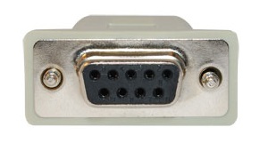
Xbit Electronics - RS-232 Level Shifter with DB9 Connector
Note: The Xbit RS-232 level shifter is no longer available. Any RS-232 level shifter that supports an input voltage down to 3 VDC should work juts fine. Here are a couple of examples:
;) (click image to enlarge)
(click image to enlarge);)
I used the following jumper wires to connect between the level-shifter and the Raspberry Pi GPIO header. The Xbit level-shifter comes with a 5 pin header that you can solder directly on to the circuit board. Mine is soldered on to the bottom of the level shifter so that I can insert it directly into the prototyping breadboard. If you are not using a breadboard, then it is probably more convenient to solder the 5 pin header to the top of the Xbit circuit board.
I also used a prototyping breadboard to make my connections, but you could just as easily solder leads to the level-shifter if you want a more permanent solution. Do not solder wires to the GPIO header, that is not a good idea. Use either these prototype push pin connectors or a press-fit connect to interface with the GPIO header.
;) (click image to enlarge)
(click image to enlarge)
This level-shifter uses a source supply (VCC) voltage of 3.3-5VDC. Fortunately the Raspberry GPIO includes a pin that provide the 3.3 VDC neccessary for the VCC connection on the level-shifter. The next three wiring connections are as simple as it gets ... Ground to Ground, TX to TX, and RX to RX. A wiring diagram and close up photos are included below to help provide a clear picture of the connections.
;) (click any image to enlarge)
(click any image to enlarge)
;)
;)
;)
Here are a few alternatives to the XBit level shifter including an option without the DB9 connector and a USB option.
- https://www.sparkfun.com/products/11189
- https://www.sparkfun.com/products/449
- https://www.sparkfun.com/products/718
(NOTE: I have not personally used or tested these alternative options but based on the specs they should work just fine. Also when connecting a level shifter, please take note of the source voltage required to drive the level shifter. Some are 5VDC only and other may support 3.3VDC. Make sure to get one that support 3.3 VDC and connect it to appropriate 3.3 VDC source voltage pin on the P1 header!)
Connecting to the Raspberry Pi Console
Both the Debian "Squeeze" and Raspian "Wheezy" images by default include support for accessing the shell by connecting a terminal emulation program to the serial port. Just connect a straight thru serial cable (not a null modem cable) between the computer and your new DB9 port on your Raspberry Pi. Open a terminal emulation software such as Hyperterminal, Procom Plus, or Indigo Terminal Emulator and connect to the serial port using settings "115200, N, 8, 1". You may need to press the enter key a time or two to see the prompt. Authenticate using your credentials and you are good to go.
Enjoy the world of serial connectivity!
 Robert Savage
Use the Serial Port in Software
http://www.irrational.net/2012/04/19/using-the-raspberry-pis-serial-port/
Robert Savage
A new article has been posted that provides additional RS232 serial interface options, hardware, and wiring digrams: Raspberry Pi - RS232 Serial Interface Options (Revisit)
Reader Comments (16)
Whether it is possible to make 4 such rs232 ports like this
@Karthik,
The Raspberry Pi only supports a single UART for serial communication. To add additional serial port capacity to your Pi, you will need to use USB to serial port adapters or interface with some more complex hardware using SPI/I2C bus. You best bet may be to find a 4 port serial hub that can connect to the Pi via USB. (If the serial to USB hub is not self powered, then you may have to also use a powered USB hub to provide sufficient power to the serial USB hub)
Thanks, Robert
hmmm standard RS 232 uses -+ 5 up to 12 V, right
TTL is 0/5V
uart TTL as on the Rpi) is 0/3.3 V
--- so the levelshifter has to be used with 3.3 V not with 5V as you suggest.
you might kill your rpi with the 5V on the input linr (which goes direct to the processor)
read here:
http://mrpjevans.com/2012/10/rs232-on-the-raspberry-pi-to-a-psion-5/
@masterhit,
Great catch and thanks for posting. I guess I originally thought that the level shifter needed the 5 VDC to provide enough voltage for driving the high side for RS232 communication. I did not realize that it was using this as a reference voltage for the low side. I guess I should have read the data sheet on the chip. I did measure the voltage on the RX/TX lines back to the Raspberry Pi and (as suspected) I noticed that some lines were above the safe 3.3 VDC voltage. Yikes! Fortunately, the voltages were not at a full 5 VDC and it seems the Raspberry Pi can deal with a little overvoltage on these lines as none of my three Pis seem to be no worse for wear. (No magic blue smoke escaped!)
I may have been led astray by some other articles that also suggest using the 5 VCD line, check these out:
http://learn.adafruit.com/adafruits-raspberry-pi-lesson-5-using-a-console-cable/connect-the-lead
http://www.rpidevel.org/2012/06/connect-serial-port-to-raspberry-pi.html
I have updated the articles to use the 3.3 VDC pin instead of the 5 VDC pin with and retested everything. All is working fine.
Thanks again, Robert
I looked at the Adafruit article. The big difference there is that they are connecting a USB plug, not an RS232.
The USB interface uses 5V by design.
Still, this is a spiffy little board. I may have to aquire one.
I think the hi side of the USB interface can be powered from the USB bus. On the low side you probably want to play it safe using the 3.3 VDC source pin. It seems to work just fine on either the 3 VDC or 5 VDC, but the voltages measured coming back into the Pi on the TX and RX pins did exceed 3.3 VDC. So while it did not seem to damage anything (luckily), I think the 3.3 VDC source is probably the safe and "correct" option.
Thanks, Robert
is it OK I used your wiring picture on my blog?
http://netzherpes.de/blog/index.php?entry=entry130203-180952 (with a source link, of course)
Contact me if not, please
@masterhit,
No problem on the use of the images; you did give proper attribution.
Thank You,
Robert
After various changes (boot / cmdline.txt + etc / inittab) According to the information, the launch of "minicom" remains offline!
My system runs on <raspbian 2.27> I2C and GPIO devices are operating normally.
Line RS232 is connected through a <max3232CPE> via com1 my PC.
Can you give me an advice
thank you
the line has to be "free", so try to comment out the inittab lline and the config.txt thing
try to start minicom as root (sudo foo)
masterhit
The serial polarity between a PC and the Pi is reversed so the level shifter alone will not work. The PC is RS-232 alternating between plus and minus 5 volts and resting at minus 5, the Pi uses TTL logic at 3.3 volts, that is the resting polarity is High. I am using the Adafruit 8 channel level converter, running minicom, commented out inittab per instructions. No Cookies
the most important is as soon as you bring in a machine and a person, it becomes inherently unsafe and you have to manage the risk... cable supply
Hi,
I want to communicate with an equipment via RS232. here is the technical specs of the equipment I want to communicate to:
baud rate = 9600
start/stop bits = 1 start bit, 1 stop bit
data length = 8 bits
parity bit = no
type = voltage level only
anybody can help me with this?
I'm trying to get a grip on this setup, using the example software given here: Serial communication article.
I'm compiling the source code through NetBeans and install it on my RPi. That all works fine.
Next, I've installed Indigo Terminal Emulator (that's the only emulator I know that allows you to give input in a separate field while the output is shown in the main output window). I connect my PC through a USB-to-Serial converter assigned to COM3 on my computer, to the RPi according the schemes given above. So far, so good.
Next, I'm starting the application on my RPi through a Putty SSH window on my PC. I see the Current Time..., Second Line and Third Line text appearing on the Indigo serial emulator output window which is connected to the serial port on my RPi 2B. I also see on my SSH window the explanation given in the SerialExample application (Title, Press CTRL-C TO EXIT, Connecting to... and so on).
However, when I type something in the separate field on the Indigo serial emulator program, I do see the text [HEX DATA] and [ASCII DATA] appearing in my SSH screen, but there's no text shown next to it.
In other words, whatever I type into the separate input field on the Indigo serial emulator, I never see it as feedback in the listener which is implemented in the SerialExample java file.
Any idea why this behaviour?
@GeetVc,
I apologize for the delay, your post was flagged as SPAM and I did not see it until just now.
Were you able to get past this issue? If not, I can setup a similar environment and test it out here.
Thanks, Robert
Hi Robert,
I am trying to use Raberry PI as a connector to pull the data from Veedor-Root tank monitor TLS-350 model. It has 24 pin connector to be able to connect TCP/IP card to that monitor. It is male 24 pin connector similar to what we have on the Rasberry PI. Does this API work to make the serial connection between Pi and TLS-350. Please let me know your comments. thank you.