


Bypass Factory Amp/Crossover in 2002 Chevy Tahoe

This article strays a bit from home automation, but it was a small project that I completed recently and felt that others could benefit from a detailed write up with step-by-step instructions and pictures.
I recently found myself needing to replace almost every speaker in my 2002 Chevy Tahoe (non-Bose sound system). The factory speakers were all blown and sounding pretty pitiful. In fact I did not realize how bad it was until I removed the old factory speakers and noticed cone separation on every door speaker and the factory subwoofer.
In addition to replacing the speakers, I came across a forum post on z71tahoe-suburban.com that discussed bypassing the factory amplifier for each of the door speakers. It turns out that all the door speakers are routed thru the factory amplifier. I am not sure that it provides amplification to the door speakers, but it does have an internal crossover that removes much of the bass from the audio signal. Since I replaced all the door speakers with a better set of component speakers capable of handing more of the full audio range, I did not want the factory amp/crossover restricting the audio signal from the head unit (receiver) to the door speakers.
The forum post included a detailed set of instructions on how to build an adapter cable that will plug directly into the factory wiring harness and the factory amplifier and bypass the factory crossover for the four door speakers. This bypass cable does still send audio and power to the factory amplifier for the rear cargo area subwoofer and pillar tweeters. (If you don't need the factory amp because you are using an after-market amplifier, then you may choose not to include that portion of the cable or just not plug the adapter back into the factory amplifier.) This is a 100% non destructive modification to the Tahoe. This bypass adapter can be removed at any time.
Parts List
;) (click image to enlarge)
(click image to enlarge)
The following parts are required.
Approximate Cost: $20-25 USD
Total Time: 1-2 hours
NOTE: You may notice that these wiring adapters describe that they are for a Saturn vehicle. Just ignore that, we are not going to use them as they are wired, we are going to reconfigure the wiring. We just need these as they are the correct connectors that will work with the Tahoe's factory wiring harness and factory amplifier.
Tools & Supplies
I used the following tools and supplies to complete this project:
;) (click image to enlarge)
(click image to enlarge)
- Wire Cutters
- Wire Strippers
- Small Flat Screwdriver
- Small Paperclip
- Large Paperclip
- CD/DVD Drive Eject/Release Tool (optional)
- Solder Iron
- Solder
- Solder Paste (optional)
- Small Nylon Wire Ties (optional)
- Assorted sized and color heat shrink tubing
- Heat Gun (or hair dryer, or cigarette lighter)
- Digital Multi-meter for continuity testing (optional)
- Table/Bench Vise (optional)
- Helping Hands with Alligator Clips (optional)
NOTE: If you are not comfortable with soldering, you could use wire nuts (twist on wire connectors, b-caps) instead to make each wiring connection. This take up more room, but is perfectly viable. Just make sure to use electrical tape or some means to ensure that the wire connectors don't vibrate loose and fall off over time.
Assembly
We are basically going to use the two Metra GM connectors to create a bypass cable that will be installed in between the Tahoe's factory wiring harness and the factory amplifier/crossover.
<< STEP 1 >> - Disassemble the Metra 70-2002 Connector
The first step is to remove all the existing pins and wires from the Metra 70-2002 connector. The pins are released by inserting a small paperclip below each pin and using a push and pull technique on the wire until the pin is released. Don't use force to remove these pins, we will need to reuse each pin and wire.
;) (click any image above to enlarge)
(click any image above to enlarge);)
;)
<< STEP 2 >> - Disassemble the Metra 71-2002 Connector
The next step is to disassemble the Metra 71-2002 connector. Before removing the pins and wires, we must first remove the two retaining clips (gray and blue). Lets start with the gray clip. Gently insert the end of a small flat screwdriver between the connector and the clip's retention clasp. Repeat this for each side of the clip. Once released, pull the clip towards the rear of the connector to remove it. Next we need to remove the blue clip. For the blue clip we must insert the end of the screwdriver to release the retention clasp from the front side of the connector. Repeat this on both sides and then gently pull back the clip towards the rear of the connector to remove it.
;)
;)
;)
;)
(click any image above to enlarge)
With the two clips removed, we can now remove each pin and wire. To remove the pins in this connector, insert either the end of the large paper clip or the end of a CD/DVD disc removal tool into the face of the connector as show below to release the pin. (I found that the diameter of the CD/DVD disc removal tool was slight larger than the paperclip and was a little easier to use.) Use the push and pull technique on the wire to remove it from the connector. Again, don't use force to remove these pins, we will need to reuse a few of the pins and wires. The pins will easily slide out towards the rear of the connector once properly released.
;)
;)
;)
;)
(click any image above to enlarge)
<< STEP 3 >> - Rewire the Connectors
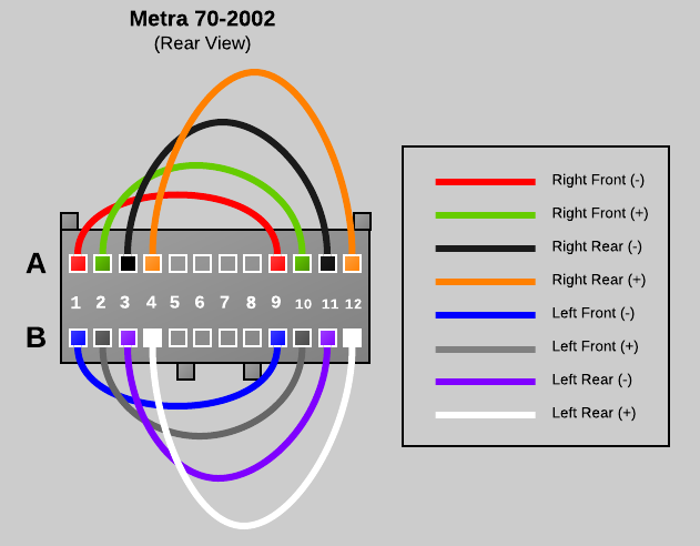
The next step is to reinstall the wiring between the Metra 70-2002 connector and the Metra 71-2002 connector. The wiring diagram below is what we will be building.
;)
Wiring Connection Legend
- Right Front (Negative) - [70] A1 to [70] A9 - RED
- Right Front (Positive) - [70] A2 to [70] A10 - GREEN
- Right Rear (Negative) - [70] A3 to [70] A11 to [71] A11 - BLACK
- Right Rear (Positive) - [70] A4 to [70] A12 to [71] A12 - ORANGE
- Power Antenna - [70] A5 to [71] A5 - YELLOW
- Left Front (Negative) - [70] B1 to [70] B9 - BLUE
- Left Front (Positive) - [70] B2 to [70] B10 - GRAY
- Left Rear (Negative) - [70] B3 to [70] B11 to [71] B11 - PURPLE
- Left Rear (Positive) - [70] B4 to [70] B12 to [71] B12 - WHITE
WIRE 1 - RIGHT FRONT SPEAKER - NEGATIVE (A1 to A9)
Note that the red wire removed from the Metra 70-2002 Connector includes three pins and two short and one long wire segments. Cut the second short wire segment as close as possible to the pin connector so that you have a single short segment with two pins attached. Next, insert the pins into the rear of the Metra 70-2002 Connector in positions A1 and A9. If the pin does not stay in place, you may need to take the screwdriver and bend the clasp on the pin back so that it can catch properly.
;) (click any image above to enlarge)
(click any image above to enlarge);)
;)
WIRE 2 - RIGHT FRONT SPEAKER - POSITIVE (A2 to A10)
Wire 1 was the easy one, the remaining wires will have to be soldered together (or connected using an alternate electrical connector). Basically we need to connect two of the wires with pins together to create a single wire with a pin on each end. Wire two is a simple straight connection using the green and green with black stripe wire leads from the Metra 70-2002 connector. I trimmed the lengths down to eliminate bulk, but that is optional. Cut, strip the insulation and solder the two ends of the green leads so that you end up with a single wire with a pins on each end. Insert a length of heat shrink tubing around the connection and heat to shrink. Finally insert the pins into position A2 and A10 of the Metra 70-2002 connector.
;) solder two leads
solder two leads
;) place heat shrink
place heat shrink
;) heat to shrink
heat to shrink
;) insert into connector
insert into connector
WIRE 3 - RIGHT REAR SPEAKER - NEGATIVE (A3 to A11 to A11)
Wire 1 and wire two were straight connections that bypass the factory amplifier completely. Wire three is slightly different because it also feeds the amplifier the rear audio signal so that the factory amplifier can drive the cargo area subwoofer and pillar tweeters. If you do not want to use the factory amplifier at all you can leave out the A11 connection to the Metra 71-2002. The next wire is a connection using the black and black with white stripe wire leads from the Metra 70-2002 connector and the black wire from the Metra 71-2002 connector. Cut, strip the insulation and solder the three ends of the black leads so that you end up with a wire with two Metra 70-2002 pins and one Metra 71-2002 pin. Before soldering make sure to stage a length of heat shrink tubing around the connection and after soldering slide the heat shrink tubing into place and heat to shrink. Finally insert the pins into position A3 and A11 of the Metra 70-2002 connector and also A11 of the Metra 71-2002 connector.
;) 70-2002 close up
70-2002 close up
;) both connectors
both connectors
;) 71-2002 close up
71-2002 close up
WIRE 4 - RIGHT REAR SPEAKER - POSITIVE (A4 to A12 to A12)
Repeat the same steps as wire three using the orange and orange with yellow stripe wire leads. Insert the pins into position A4 and A12 of the Metra 70-2002 connector and also A12 of the Metra 71-2002 connector.
;) 70-2002 close up
70-2002 close up
;) 71-2002 close up
71-2002 close up
WIRE 5 - POWER ANTENNA (A5 to A5)
Wire 5 is a simple straight through connection from A5 of the Metra 70-2002 connector to A5 of the Metra 71-2002 connector using the yellow wire leads
;) 70-2002 close up
70-2002 close up
;) 71-2002 close up
71-2002 close up
WIRE 6 - LEFT FRONT - NEGATIVE (B1 to B9)
WIRE 7 - LEFT FRONT - POSITIVE (B2 to B10)
Wire 6 and 7 are both simple straight bypass connection just like wire 1 and 2 except that they are installed on the "B" side of both connectors. Wire 6 uses the blue with yellow strip and the tip of the red wire from the Metra 70-2002 connector. There were not two blue leads and we need to reuse every pin, so I used just the tip of the remaining red wire lead and trimmed off the extra red wire. See the photo for details. Wire 6 should be inserted into positions B1 and B9 on the Metra 70-2002 connector. Wire 7 uses the gray and gray with black strip wire leads from the Metra 70-2002 connector and should be inserted into positions B2 and B10 on the Metra 70-2002 connector.
;) Wire 6 - Blue
Wire 6 - Blue
;) Wire 7 - Gray
Wire 7 - Gray
WIRE 8 - LEFT REAR - NEGATIVE (B3 to B11 to B11)
WIRE 9 - LEFT REAR - POSITIVE (B4 to B12 to B12)
Wire 8 and 9 are identical to wires 3 and 4 except that they are installed on the "B" side of both connectors. These wires provide the rear audio signal for the factory amplifier to deliver sound to the factory subwoofer and pillar tweeters in the cargo area. Wire 8 uses the purple and purple with black stripe wire leads from the Metra 70-2002 connector and the purple with black stripe wire from the Metra 71-2002 connector. Wire 8 should be inserted into positions B3 and B11 on the Metra 70-2002 connector and position B11 on the Metra 71-2002 connector. Wire 9 uses the white and white with black stripe wire leads from the Metra 70-2002 connector and the white wire from the Metra 71-2002 connector. Wire 9 should be inserted into positions B4 and B12 on the Metra 70-2002 connector and position B12 on the Metra 71-2002 connector.
;) Wire 8 (70-2002 close up)
Wire 8 (70-2002 close up)
;) Wire 8 (71-2002 close up)
Wire 8 (71-2002 close up)
;) Wire 9 (70-2002 close up)
Wire 9 (70-2002 close up);) Wire 9 (71-2002 close up)
Wire 9 (71-2002 close up)
WIRING COMPLETE
That all the wiring steps, next, we will test the connections and complete the assembly.;) Wiring Completed (click image to enlarge)
Wiring Completed (click image to enlarge)
<< STEP 4 >> - Testing
If you have a multi-meter or continuity tester, its a good idea to test all the pins to make sure that the connectors are wired correctly before installing into the Tahoe. Set the multi-meter to continuity testing mode and then test the following pins in the Metra 70-2002 connector and make sure there is a connection between them. Also touch the other pins to ensure that no other pins have a connection for each test.
- A1 to A9
- A2 to A10
- A3 to A11
- A4 to A12
- B1 to B9
- B2 to B10
- B3 to B11
- B4 to B12
Next let's test the Metra 71-2002 connector. To do this you can use the small paper clip to insert into each pin for testing. Ensure the following connection are valid:
- Metra 70-2002 A5 to Metra 71-2002 A5
- Metra 70-2002 A11 to Metra 71-2002 A11
- Metra 70-2002 A12 to Metra 71-2002 A12
- Metra 70-2002 B11 to Metra 71-2002 B11
- Metra 70-2002 B12 to Metra 71-2002 B12
;) Multi-meter / Continuity tester
Multi-meter / Continuity tester;) test Metra 70-2002
test Metra 70-2002;) test Metra 71-2002
test Metra 71-2002
<< STEP 4 >> - Tidy Up
All tests passed? Great! Let's finish by re-installing the retention clips in the Metra 71-2002 connector and and adding a few nylon wire ties to tidy up this bypass connector.
;) blue clip
blue clip;) gray clip
gray clip;) Metra 71-2002 - complete
Metra 71-2002 - complete
Install a few nylon tie straps and trim all the excess strapping.
;)
Installation
Now that your have constructed the bypass adapter, the installation inside the truck is very simple. Empty the glove box and then depress the right side towards the drivers side of the vehicle to allow the glove box door to open completely and drop open.
Next, locate the factory amplifier directly to the right of the cabin air filter on the right side of the glove box cavity.
;)
;)
Next, release the mounting retention clip located on top of the amplifier.
;)
;)
Tilt the amplifier up to gain easier access to the wiring connectors plugged into the amplifier. Unplug the lower wiring connector from the amplifier. There is a release on the back side of the connector, you must depress this release before the plug can be removed from the amplifier.
;)
;)
Insert the Metra 70-2002 connector on the bypass adapter into the vehicles wiring harness. Insert the other end of the bypass adapter (the Metra 71-2002 connector) into the factory amplifier. Don't worry, you can't screw this up, the plugs only fit in their correct locations.
;)
;)
Tuck the bypass adapter away above the amplifier so that does not interfere with the glove box. Put the amplifier back in place and re-attach the retention latch and then raise the glove box and fire up your stereo for a test. That's it -- we are all done!
;)
More Information / Source
More information about the wiring harness in the Tahoe and more specific details about this adapter can be found in this document:
Please note: the wiring coloring scheme used in this document is different than what is posted in this article. The article used the best mix of colored wires based on what came in the Metra connector packages and trying to remain as consistent as possible for all connection leads.
This document was originally posted on this forum posting:
 Robert Savage
If you are not interested in using the 2002 Tahoe's factory amplifier, rear pillar tweeters, and factory sub, then you only need the Metra 70-2002 connector and not the Metra 71-2002.
The wiring is bascially the same except that no wire leads extend to the second connector. This version of the adapter just bypasses the factory amplifier/crossover and sends the pure unfiltered audio signals to all the door speakers.
UPDATE 2019-07-02
A number of user comments suggest that you can simply purchased Metra #70-2021 if you wish to do a complete bypass of the factory amp. I have not personally verified or tested this, but it may be worth a try or further investigation for an easier off-the-shelf install.
Reader Comments (160)
Is it possible to tie the rear speakers and subwoofer to the door speakers also? I would like to keep their functionally as rear speakers tied to the rear door speakers.
Thank you so much for this write-up. I ended up using it for a slightly different application, but it could not have worked any more perfectly. Instead of just bypassing the factory amp, I wired this little guy http://www.crutchfield.com/p_020XC1410/Clarion-XC1410.html?tp=115 into the harnesses to power a new set of Kicker 2-way speakers. I left the factory sub and rear tweeters as they were from the factory, and I couldn't be happier with how it all turned out. Your write-up made the job 1000% easier.
Looking to use your by-pass wiring as a tutorial to use the small tahoe amp just to run a small sub woofer in the back of a t10 blazer I'm fixing up.The wiring details are great,but just one question comes to mind,what about the pin A6 amplifier gain control.What is it hooked to and does it need to be hooked up?
Thank you
Does this bypass work on a 2001 Tahoe with Onstar?
I have a 2003 Chevy Tahoe with a double din radio I'll be replacing with a pioneer deck with android, ipod control, usb and line input. I have the adapter plate for mounting the single din radio, the Rp3gm11 radio replacement interface to retain factory chime that comes with the complete harness to hook to factory hookup and the radio a pioneer DEH-6800BT, 4 Rockford Fosgate Prime R1 Full Range Speakers model 165x3, 2 pairs of adapter harness for plugging the speakers in so I don't have to cut factory door wiring.
My next question is how do I know if I have a amp and subwoofer from the factory that I'd need to bypass or just remove and add my own as adding one sub has been something I'm considering. I'd like to use the factory panels on one side or another in the cargo area and would need to know how to select the right size and install it. I also would mount the amp under the split 60/40 rear fold down seats in the 2nd row. I rarely have the 3rd row seating in as my kids are in the teen stages so we don't haul their friends as much anymore or should I say as many friends at once anymore.
I stumbled across this article and it got me wondering if I even had an amplifier and sub in my Tahoe. If so this will definitely be a handy article. Any and all comments are appreciated. Thanks! Dtnel
Robert,
any chance you could make one I could buy??
thx!!
question: are the front door tweeters crossed-over through the amp or do they have a capacitor on them??
thx
@Jared
Q: Does this bypass work on a 2001 Tahoe with Onstar?
A: It works on my 2002 Tahoe with Onstar. Of course its the old analog version of Onstar so it is not connected to service.
Thanks, Robert
@Chris
Q: any chance you could make one I could buy??
A: Sorry, I'm not in the position to build and sell these cables. It was just a hobby project for my personal Tahoe :-)
Q: are the front door tweeters crossed-over through the amp or do they have a capacitor on them??
thx
A: I'm not really sure. I'm not a car audio expert, but I don't recall any capacitors on the OEM front speakers when I ripped them out and replaced them.
Thanks, Robert
@Dtnel,
I would just pull down the glove box door and look for the factory amp hidden behind the glove box compartment. Take a look at the photos in the blog post to get an idea of what you are looking for :-)
The rear sub is on the left (drivers) side when facing from the rear cargo area behind the plastic panels in my 2002. I replaced my sub, but am still using the factory amp. A new amp would probably improve the audio considerably but I did not want to run new wiring for power and find a place to hide the amp.
I wish I had a double din :-)
Thanks, Robert
Any idea if this would work for a 2002 Chevy Avalanche???
Just completed the bypass per your instructions. Worked in my 2001 Yukon XL. I replaced the door speakers which had outlived their useful life by many years. If my factory radio had Sirius XM and BT I wouldn't bother to upgrade the HU as it sounds so much better with this bypass in place. Thanks for creating the clearest step-by-step instructions that I have ever seen.
@Jacob,
No idea on the Avalanche, but highly probable.
@Z-Man
Glad these instructions helped out!
Thanks, Robert
Thank you so much! This is one of the best online explanations I have ever seen. This crossover bypass worked flawlessly. I also replaced the subwoofer with a $20 Pyle subwoofer and I am extremely happy. I went from being severely disappointed with my 2002 stereo system to being very happy. Thank you, thank you, thank you!
@138,
You are welcome! I'm glad this article is still helping people.
I just read ur article and an going to do it. I have a 2000 Tahoe that the rear speakers stopped working. car toys said it is the oem amp.
my question is above the oem amp is another unit. silver in color and has 2-32pin plugs on it. do u know if this is part of the oem amp or is it something else.
thanx for any info u can give me
Hey all:
Bought a 2002 Tahoe. Only the front speakers worked. I removed the rear door panels and the speakers were done as expected so I replaced them with some nice Pioneers. (PLUS the stereo was an OEM up-fitted for a digital input. I bought a stereo and kit to install, not expected, the rears didn't work again. I removed the AMP and bought a Metra 70-2054 and thought I could make it work. I gave up. Need some advise. I'm a seasoned Old School installer, this is tough.
JT
I installed me deck a 4 channel amp for front and back speakers and ran my rca's to unr deck and installed a 2nd amp foot my subs with of course another set of rca's to the back of the deck. Radio will power up when I start the truck and if the front and back speakers do actually come on they only stay on till I put it in drive and go about 10 feet then speakers shut off but subs will stay on and no matter what I do I can't get them back on till the truck has been shut off for a period of time. Sometimes they won't come back on for a day or 2 then will stay on until I get back home and put it on park then they shut off again. For the record I know my amps are good, even tried a different amp with same issue, please help is roof cause of that factory amp?
I installed me deck a 4 channel amp for front and back speakers and ran my rca's to unr deck and installed a 2nd amp foot my subs with of course another set of rca's to the back of the deck. Radio will power up when I start the truck and if the front and back speakers do actually come on they only stay on till I put it in drive and go about 10 feet then speakers shut off but subs will stay on and no matter what I do I can't get them back on till the truck has been shut off for a period of time. Sometimes they won't come back on for a day or 2 then will stay on until I get back home and put it on park then they shut off again. For the record I know my amps are good, even tried a different amp with same issue, please help is roof cause of that factory amp?
Robert,
Thanks SOOOoo much. I just used the one connector as the Sub was shot. The factory amp was also shot. Your write up made it so simple to just power the front speakers by bypassing all the rest. My Sony head unit now powers the front speakers with sound I NEVER had before. Amazing sound.
Thanks again, I never could have done it without this perfect write and perfect pictures.
Pat