


 Print Article
 Raspberry Pi - John Jay's 8 LED & Button Breakout Board

Overview
Shopping List
Parts for Optional Ribbon Cable & Connector (below)
- 1 @ 26P ribbon cable (1 meter or less)
- 2 @ 26P female IDC connectors (press-fit)
- 1 @ 26P box header IDC male sockets (right angle or straight)
Tools
- Wire snips (Hakko CHP170 Micro Cutter, 16AWG Clean Cut)
- Solder Iron (Weller WLC100 40-Watt Soldering Station)
- Solder (lead-free)
Assembly
Assembly instructions can also be found on John's website: http://mypishop.com/Pi%208%20LED%20&%208%20Button.html
;)
The kit includes the following components:
- 1 @ printed circuit board
- 8 @ green LEDs
- 8 @ momentary/normally-open pushbutton micro-switches
- 2 @ resistor networks
- 1 @ 26 pin PCB mount female header
(not pictured)
- 1 @ peel-and-stick on rubber bumper
(not pictured)
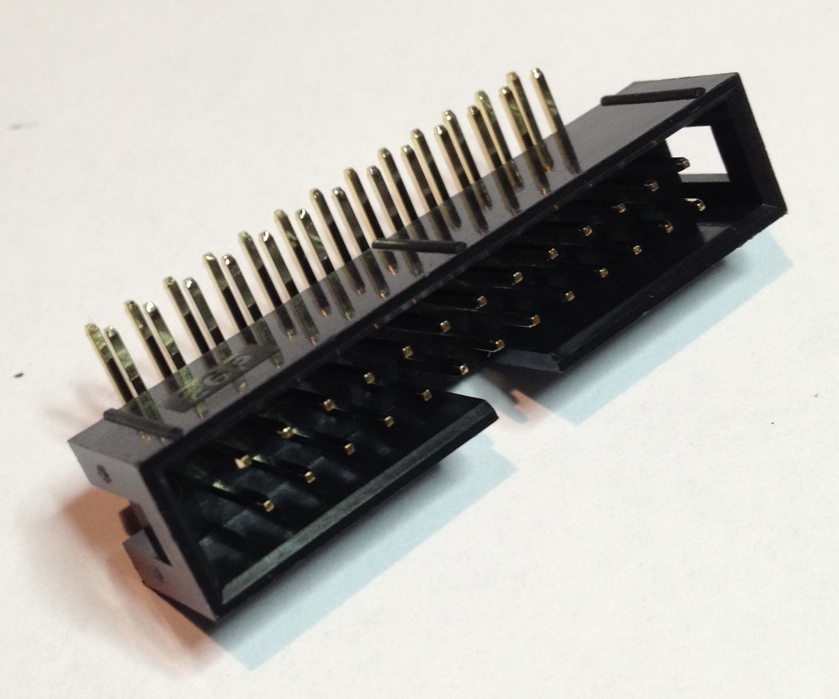
In addition to the parts provided in the kit, I also used a right-angle 26P male box header socket for connecting a 26P ribbon cable to the Raspberry Pi.
TIP: Click any image to enlarge and view a high-resolution photo.
STEP 1 > Insert the 26P male header socket in the position at the edge of the board and then solder the pins in place on the bottom side of the board. NOTE: If you are not using this optional IDC box socket connector and you are using the supplied female header, then be aware that it should be mounted to the bottom of the board and soldered in place on the top.
;)
;)
STEP 2 > Insert one of the A102J resistor networks into the RP1 position on the top of the board. Solder in place on the bottom of the board. You can bend the pins over to help hold the component in place while you solder.
;)
;)
STEP 3 > Insert the second A102J resistor network into the RP3 position on the top of the board. Solder in place on the bottom of the board.
;)
;)
STEP 4 > Next we will install the 8 LEDs. The LEDs have a short lead (cathode) and long lead (anode). The long lead (anode) should be insterted into the hole closest to the 26 pin header connector. See the photos below to make sure you have them in the correct orientation.
;)
;)
Insert the 8 LEDs in position and then carefully flip the board and solder each LED in place. TIP: You may find it easier to solder just one lead of each of the LEDs and then check the LEDs from the top and adjust any for final positioning.
;)
;)
After soldering each of the LEDs use a pair of wire snips to trim the excess lead wires.
;)
;)
STEP 5 > Next we will install the momentary buttons. Each button has four pins that will insert into the board. Press each switch in place firmly to fully seat the switch.
;)
;)
Once the switches are placed, flip the board and solder each of the pins on all the switches.
;)
That's it. Now you have a complete assembled board ready for use with your Raspberry Pi.
;)
;)
;)
;)
Logic
The 8 LEDs are controlled by positive 3.3 VDC TTL voltage on each of the corresponding GPIO pins. Setting a GPIO pin to HIGH will cause the LED to turn ON and setting a GPIO pin to LOW will turn the LED OFF.
When depressing one of the 8 input buttons, the closed circuit will provide a ground drain for the GPIO pin thus causing it to go LOW. When an input button is not depressed the circuit on the GPIO pin will remain floating; therefore, each of the GPIO pins used with these buttons should be configured to set their internal resistors to pull up. In software, this means that the button will remain in the HIGH state when it is not pressed and will go LOW while a button is pressed.
LED Wiring Diagram
The 8 LEDs are mapped to the P1 header on the Raspberry Pi as depicted in the diagram below.
;)
Button Wiring Diagram
The 8 buttons are mapped to the P1 header on the Raspberry Pi as depicted in the diagram below.
;)
GPIO Pin Cross-Reference Chart
Below is a cross reference chart to better help define the GPIO pin numbers used for each button and LED.
;)
C Sample Program
If you are interested in native C sample code, please check out this article on Gordon's Project Blog:
https://projects.drogon.net/more-buttons-and-leds/
Gordon provides a sample program based on the WiringPi library.
Python Sample Program
The following Python source example was provided by John Scuteri
https://github.com/johnscuteri/OpenSourcedButtonBoardTest/blob/master/MyTestProgram.py
Java Sample Programs using Pi4J
Below is a sample Java program for monitoring the 8 buttons on this board.
Below is a sample Java program for creating a cylon effect that cycles through the 8 LEDs on this board.
Final Thoughts
Assembling this kit was simple and takes about 30 minutes. This kit is a very convient tool to have on hand while testing and developing software for the Raspberry Pi. This kit is also a very good educational kit to begin interacting with the Raspberry Pi's GPIO pins.
Reader Comments (15)
How do you put the Java code I created a file jjLed8.jar and pasted it in but have no idea how to deal with java
@Malakai,
1.) First you have to install a Java Runtime / Development Kit on your Pi. If you are running on Raspian, then just use this command on the terminal:
sudo apt-get install openjdk-7-jdk
2.) Next, since this code depends on the Pi4J project, you must download and install Pi4J. Instructions here: http://pi4j.com/install.html
3.) Next, download once of the source Java files above. In this example we will use the cycle/cylon example. Use this command to download the raw source file and store it to a local file on your Pi from the console:
wget -O CycleGpioExample.java http://pastebin.com/raw.php?i=tVm5Ka66
4.) Next, we need to compile the Java source file. Use this command via the Pi console to compile the Java source file:
javac -classpath .:classes:/opt/pi4j/lib/'*' -d . CycleGpioExample.java
5.) Finally we can execute the Java test program using this command from the Pi's console:
sudo java -classpath .:classes:/opt/pi4j/lib/'*' CycleGpioExample
When you want to terminate the program, press CTRL-C to stop.
That's it :-)
Cylops programs works fine, thanks
Trying to use the Listener program but I don`t know if it is working.
How can I check with a browser or SSH terminal?
Sorry for a basic question but i'm a newbie.
Sorry what get is a message saying file not found but I see it in the examples directory when I try to compile it...see below
pi@raspberrypi ~ $ javac -classpath .:classes:/opt/pi4j/lib/'*' -d . ListenGpioExample.java
javac: file not found: ListenGpioExample.java
Usage: javac <options> <source files>
use -help for a list of possible options
I'm currently testing this board with my Java code using Pi4J. The outputs all work fine but I'm confused by the inputs, which are not working so well. As I understand it, the buttons pull the pins to ground via a resistor. So the inputs are floating and you need to set the PinPullResistance to OFF. If it was set to PULL_DOWN, then it would already be low.
I've tried both settings and the OFF is the only one that partly works as I'd expect but it doesn't work reliably as the input pins really need a pull up resistor to +V and this isn't present on the board. I'm seeing the odd transient because of this but it doesn't detect button pushed reliably.
If I don't use this board and connect each input pin to pin 1 on the header my code works fine. Am I misunderstanding something?
Rob
The Listener program does not work on my board but the cyclon works fine. Has anyone go the program to work?
@ Wayne,
You can just SSH to your Raspberry Pi and monitor the console output to see the results of the listener test program. Or you can connect the Pi to a HDMI monitor and see the results on screen via the console.
If you are not seeing any input, you may need to update the firmware on your Raspberry Pi. Try using the following two commands to update:
sudo apt-get update
sudo apt-get upgrade
Then reboot the Pi and try the listener test program again.
Thanks, Robert
@Rob,
Yes, when you press a button on this board, it completes a circuit between the GPIO pin and GROUND. So this means that we want to see some positive voltage on the GPIO pin when the button is not pressed. The internal PULL UP resistor should be enabled so that the pin has a positive voltage bias when the button is not depressed. Without PULL UP or PULL DOWN enabled, the PIN will be in a floating state and you will see unpredictable results. If PULL DOWN is enabled, you are giving it a bias to ground and will never see any input changes. The PULL UP resistor provides a weak positive signal on the pin and when the button is pressed the pin drains to ground. Thus the software reading the pin will see the pin in a HIGH state when the button is not pressed due to the positive voltage bias and then it will switch to a LOW state when the button is pressed and the pin is drained to ground.
Thanks, Robert
Thanks so much for posting this. It has been quite useful. Has anyone tried out John Jay's 32-bit "Protect My Pi" board? That's my next project. If there are already java samples floating around, I haven't found them and would love a pointer.
Sorry for responding to my own comment, but I just found MCP23017GpioProvider.java in Pi4J and the example MCP23017GpioExample.java. These are a great start. Let me change my question. Before using this do I need to un-blacklist i2c in raspi-blacklist.conf and load the i2c module via /etc/modules?
Thanks,
Joe
@Joe,
Glad you found the MCP2317 provider. There is also a simple example Java program available here that implements the provider:
https://github.com/Pi4J/pi4j/blob/master/pi4j-example/src/main/java/MCP23017GpioExample.java
I have been meaning to write up an article on the assembly and usage of the Protect-My-Pi board, but have not gotten around to it yet. Yes, you will need to un-blacklist the i2c kernel driver and reboot. I think that is all you have to do --- its been a while since I set this up.
Thanks, Robert
@Robert,
Thank you for the tips. I'll try it out and let you know when I get it working.
Joe
I bought the board for a project. I wanted to work with Python as that is what is recommended for the Raspberry Pi and I would then be forced to learn a new language. I had problems with the RPI.GPIO and found RPIO to be a better tool set to work with as it allows the resistor value changing. I made my own tester program in Python inspired by your button tester program and incorporating the LEDs. I felt linking my Git here might help future viewers of this site if they preferred to program in Python. The following is a link to my Git
https://github.com/johnscuteri/OpenSourcedButtonBoardTest/blob/master/MyTestProgram.py
@John,
Thanks for the link. I'll include it up in the main article body as well.
Thanks, Robert
I'm 70 and have many years of computers under my belt. This week I built the LED board and I'm trying to test it with the Python program you supplied . I'm a newby at RPI and Linux and Python.
Your program couldn't find "RPIO"
After some reading on the web, I ran the following command successfully:
sudo apt-get update
sudo apt-get install python-dev
sudo apt-get install python-rpi.gpio
As your program again failed to find RPIO, I did some more research on the web and then issued the following command:
sudo apt-get install RPi.GPIO.RPIO
with the following result:
Reading packagel lists.... Done
Building dependency tree.... Done
Reading state information... Done
E: Unable to locate package RPi.GPIO.RPIO
E: Couldn't find package by regex "RPi.GPIO.RPIO'
Can you help please?
Thanks.