Print Article
 ModMyPi PiOT Relay Board Review


![]() ModMyPiIn this article, I am reviewing the new ModMyPi PiOT Relay Board.
ModMyPiIn this article, I am reviewing the new ModMyPi PiOT Relay Board.
First Impressions
After un-boxing the relay board, my first impressions are just .. Wow! You can tell immediately that somebody really put some thought into creating a sophisticated relay board for direct use with the Raspberry Pi.
Most relay boards I have worked with have been either cheap (both in cost and in quality) relay boards with the most primitive of options or relay boards that I have hand-built using relays, transistors, resistors, diodes, capacitors, etc. The nicest in terms of quality relay board I had prior to this board was the PiFace relay board. However, it is controlled via software and SPI communication rather than direct GPIO control. So it's a very different use case.
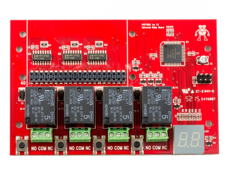 PiOT Relay Board
Where To Buy
You can purchase the PiOT Relay Board directly from ModMyPi for about $34 USD plus shipping.
Features
The ModMyPi PiOT Relay Board offers the following features:
- 4 x OMRON G5LA-1 Relays for Switching up to 10A @ 250VAC, or 10A @ 24VDC
- 4 x Tactile Buttons for GPIO/Relay Bonding
- Two-Digit 7 Segment Display for Visual Feedback & Setting Control
- Micro-controlled GPIO/Relay Setting & Switching (No Jumpers Required!)
- 40 Point Raspberry Pi GPIO Modelled Input
- 5V & 3.3V Input Compatible
- Low Holding Current via PWM ~ 100mA per Relay Board
- Stackable Relay Board (Up to 5 Without External Power)
- Multiple Start-Up Modes to Negate Boot GPIO Chatter (Delayed/Handshake)
- Pi Zero Mounting Points
Installation
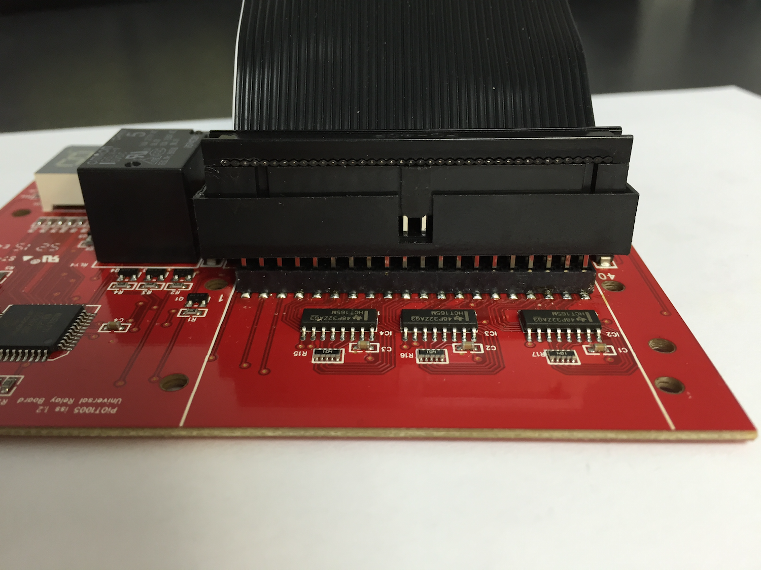
There are a number of installation options for connecting to your Raspberry Pi. You can stack mount it on top of your Raspberry Pi like most shields and add-on boards. You can use a 40-pin male connector and ribbon cable to have a flexible connection between the relay board and the Raspberry Pi. Or if you have a Pi Zero you can surface mount the PiZero on top of the relay board. The PiOT Relay Board Wiki has a page that demonstrates each option. Some options may require additional parts, so you may want to consider how you will want to mount or connect the relay board to your Raspberry Pi before placing your order.
https://github.com/modmypi/PiOT-Relay-Board/wiki/Installation
;) Stack Mount
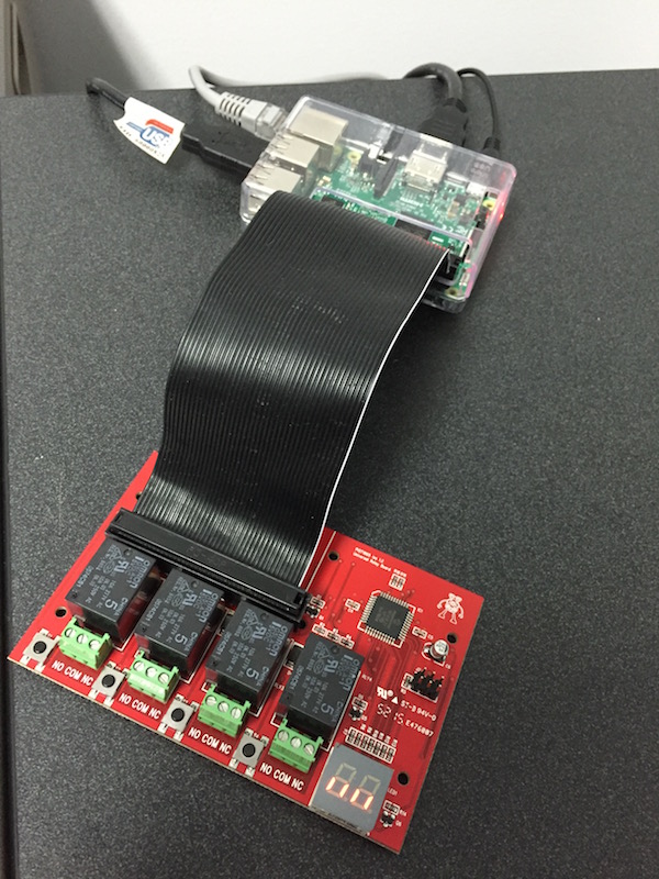
Stack Mount;) Ribbon Connecrtion
Ribbon Connecrtion
;) PiZero - Surface Mount
PiZero - Surface Mount
For my testing, I chose to insert a 40-pin male header on the top side of the relay board and use a ribbon cable to attach to my Raspberry Pi.
;)
Configuration
In order to control each of the four relays you must first access the configuration menu on the relay board and configure the pin numbering scheme.
See the the following link for details on how to access the configuration menu:
https://github.com/modmypi/PiOT-Relay-Board/wiki/Menu---Access
A detailed explanation of the pin numbering schemes and a pin mapping diagram is included in the next section of this article.
After configuring the preferred pin numbering scheme, you can then following the instructions linked below to set/assign/select the GPIO pin to control each each relay:
https://github.com/modmypi/PiOT-Relay-Board/wiki/Basics
Pin Numbering Scheme
The ModMyPi PiOT Relay Board supports a soft (software-based) mapping between each of the four relays and GPIO pins on the Raspberry Pi. The relay board allows you to configure this mapping using one of two pin numbering schemes. Instructions for configuring your relay boards pin numbering scheme can be found here: https://github.com/modmypi/PiOT-Relay-Board/wiki/Menu---Io---Pin-Numbering
- GPIO (also known as BCM or Broadcom pin numbering)
This numbering scheme denotes each GPIO pin by their actual GPIO number on the Broadcom SoC chipset. This numbering scheme is the predominate numbering scheme used by the firmware, raw C code, the GPIO device driver, the GPIO Python library and more. The SoC GPIO pins can, albeit rare, vary from model to model or RPi board revisions and may be exposed on difference physical header pins. For this reason, this is considered a direct pin mapping where there is no software abstraction layer re-mapping pins to ensure consistency across models/board revisions.
When configured for the GPIO pin numbering scheme, the relay board will display "gP" on the LED digital display.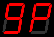
- PN (Header Pin Numbering)
This numbering scheme denotes each GPIO pin by their physical pin location on the 40-pin GPIO header. This numbering scheme is easier to follow because the pin numbers directly match the actual (address) location on the header connector. This pin numbering scheme is considered an abstract pin mapping because there is a software abstraction layer that is responsible for mapping the physical header pin number (address) back to the appropriate GPIO number on the Broadcom SoC. The WiringPi C library supports addressing by header pin numbers.
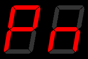
When configured for the header pin numbering scheme, the relay board will display "Pn" on the LED digital display.
You can use the diagram below to help map the pin numbering scheme you choose to the actual GPIO pins on your Raspberry Pi. This pin mapping diagrams includes both of the supported pin numbering schemes supported by the ModMyPi PiOT Relay Board as well as the WiringPi/Pi4J pin numbers in case you are using the WiringPi/Pi4J pin numbering scheme in your software. (You can click the image to download a high resolution copy of the diagram.)
;) Click the image above for a hi-resolution copy of the pinout diagram.
Click the image above for a hi-resolution copy of the pinout diagram.
Tutorial and Documentation
There is an excellent and easy to follow set of instructions available for the ModMyPi PiOT Relay Board located on GitHub:
https://github.com/modmypi/PiOT-Relay-Board/wiki
Sample Python code is also available to help get started with your relay board.
https://github.com/modmypi/PiOT-Relay-Board
I did not use the sample code, instead I tested the board using the command line commands in the following "Testing" section of this article.
Testing
After you have configured the pin numbering scheme and have set the GPIO pin assignments for each relay you are ready to test controlling the relay by toggling the GPIO pin states between HI and LOW. You can use the example Python program included in the PiOT Relay Wiki or you can simply use the following "gpio" command line instructions to test.
Export the GPIO Pin
The first thing we must do is export the GPIO pin as an output pin. To do this via the gpio utility, you must to use the BCM GPIO number. So lets use the GPIO #2 (Header Pin #3, WiringPi Pin #8) in our example.
> sudo gpio export 2 out
 Control Relay in "GP" (GPIO) Pin Numbering Mode
Now we can control the GPIO assigned relay using the following commands:
Turn the relay ON; do do this we need to set GPIO#2 to the HIGH (1) state.
> sudo gpio -g write 2 1
Turn the relay OFF; do do this we need to set GPIO#2 to the LOW (0) state.
> sudo gpio -g write 2 0
(Note, the "-g" argument used with the gpio utility instructs the gpio utility to use the BCM pin numbering scheme. Without this argument, the gpio utility would attempt to use the WiringPi pin numbering scheme by default.)
 Control Relay in "PN" (Header) Pin Numbering Mode
Now we can control the GPIO assigned relay using the following commands:
Turn the relay ON; do do this we need to set GPIO on header pin #3 to the HIGH (1) state.
> sudo gpio -1 write 3 1
Turn the relay OFF; do do this we need to set GPIO on header pin #3 to the LOW (0) state.
> sudo gpio -1 write 3 0
(Note, the "-1" argument used with the gpio utility instructs the gpio utility to use the header pin numbering scheme. Without this argument, the gpio utility would attempt to use the WiringPi pin numbering scheme by default.)
Wish List
Here are some of my thoughts as a wish list for a future version/revision of the product :-)
I wish ... that there was a way to lock down the configuration of pin assignments once you have them configured just how you want them. It's a bit too easy to accidentally re-map a pin when fumbling with the buttons.
I wish ... that pin assignment/configuration put the board into a mode where it would not toggle the configured relay state until the assignment was complete. Currently as you cycle thru the pin numbers the relay toggles immediately based on the GPIO pin state of the pin number you are cycling through.
I wish ... there was a method via software to configure pin assignments. This way a booting application could ensure the proper pin mapping for it's needs. This would make the board highly reusable across multiple projects without manual interaction to assign pins. This would especially be helpful for users who potentially just download some software application to run on their system and may not be as geeky to understand or configure relay pin assignments.
I wish ... there were 4 opto-isolated inputs on the board. The relays do a great job for outputs but often your project needs both inputs and outputs. I realize this may be an increased cost and perhaps a different SKU at a higher price point.
Final Thoughts
In closing, I just have to say this is a very nice board and a nice prototyping tool to have on hand when building a project that requires relay control via GPIO. Sure its a bit more expensive than a cheap Chinese relay board, but as with most things in life .. you get what you pay for.
I think this board is very well suited as a prototyping tool for a professional developer and also a perfect tool for for hobbyists wanting to use their Raspberry Pi's to control things and are not well versed in concepts like active-hi, active-low, coil suppression, level-shifting, etc. when interfacing to relay boards.
The design and features of the ModMyPi PiOT Relay Board are very well thought out and offer unprecedented flexibility for relay-based projects using a Raspberry Pi. The features I like most are the optional boot up modes, the soft-mapping of GPIO pins, the direct test button control and the friction connector allowing surface or bottom mount connections. I can certainly see projects where just this board and a Pi Zero together comprise an elegant and compact solution for things like remote or expanded sprinkler zone controllers and other home automation projects.
Disclaimer:
This relay board was provided to me at no cost for an honest and unbiased review.