In a previous article we discussed how to use the Twine to monitor the state of a garage door and send alert notifications via text (SMS) or email if the door had been left open for a certain period of time. In that article/project we used the built-in orientation sensor in the Twine and the Twine mounted directly to the garage door to determine garage door state. While this was a simple and elegant solution there a certain practical issues for a long term garage monitoring solution that this project did not really address.
The number one issue is battery life. Mounting the Twine directly to the garage door forces the Twine to run solely on batteries and the battery life on the Twine may be too short to be practical for a permanent installation. Personally, I prefer a physically connected powered solution so that I don't have to concern myself with battery replacements. The second practical need for my installation was the need to monitor more than one garage door. Using the previous project concept, it would require 2 Twines to pull this off. Finally, it may not be practical to mount the Twine directly to the garage door for all installations.
In this article we will address these limitations by installing the Twine to the garage wall and not directly to the door. We will use external magnetic sensors designed for garage doors and we will connect two door sensors to a single Twine unit to monitor the state of both garage doors.

Shopping List
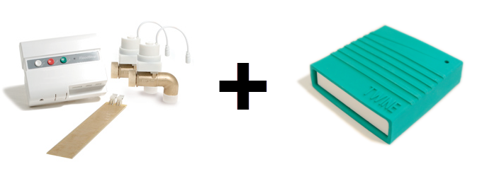
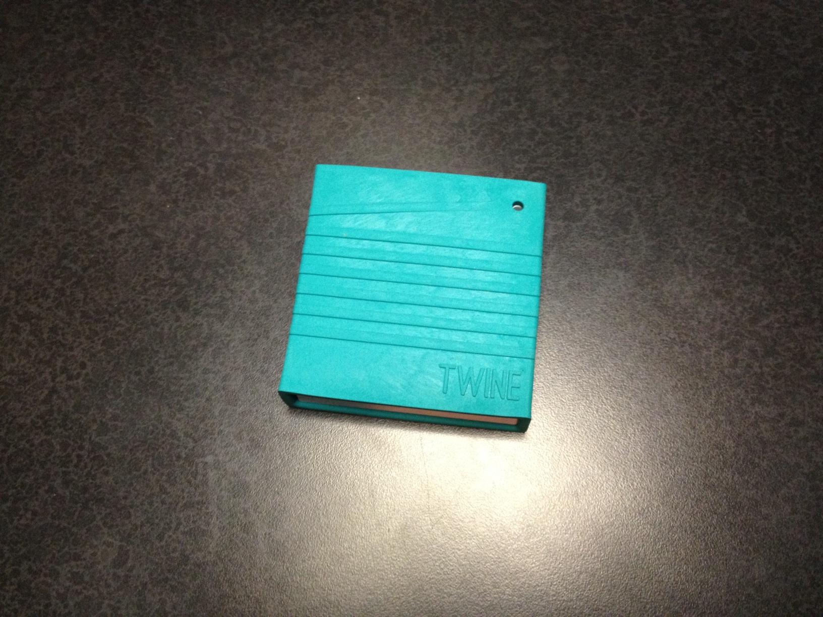
- 1 @ Twine Portable Wi-Fi Sensor
(or) Twine Portable Wi-Fi Sensor + Full Sensor Package
(or) Twine Portable Wi-Fi Sensor + Magnetic Switch
(or) Twine Portable Wi-Fi Sensor + Moisture Sensor
- 1 @ Twine Breakout Board (sensor interface)
- 2 @ Seco-Larm Overhead Door Alarm Switch (NC/NO Contact 3 Wire)
(or) Garage Contact Normally Opened or Closed - 1 @ Micro-USB Power Supply
Installation
The installation time took about 30 minutes for this project. We start with opening the garage door sensors from their packaging. These sensors support both a normally-open (NO) and normally-closed (NC) mode of operation. In this project we will use the normally-closed (NC) behavior and contacts. (Normally-closed in this application means that when the magnet is not near the sensor, the circuit is closed. When the magnet is brought in range to the sensor, the circuit becomes open.)
;)
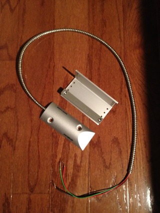
The advantage of using a sensor that is designed for use with a garage/overhead door is that its sensor range is much greater and thus more tolerant than a traditional security system door magnetic sensor. The sensor range is 3 to 4 inches. These garage door sensors are designed to be installed on a concrete floor, but in my installation, I decided to install them on the wall above the door and not go through the effort of drilling into the concrete.
;)
;)
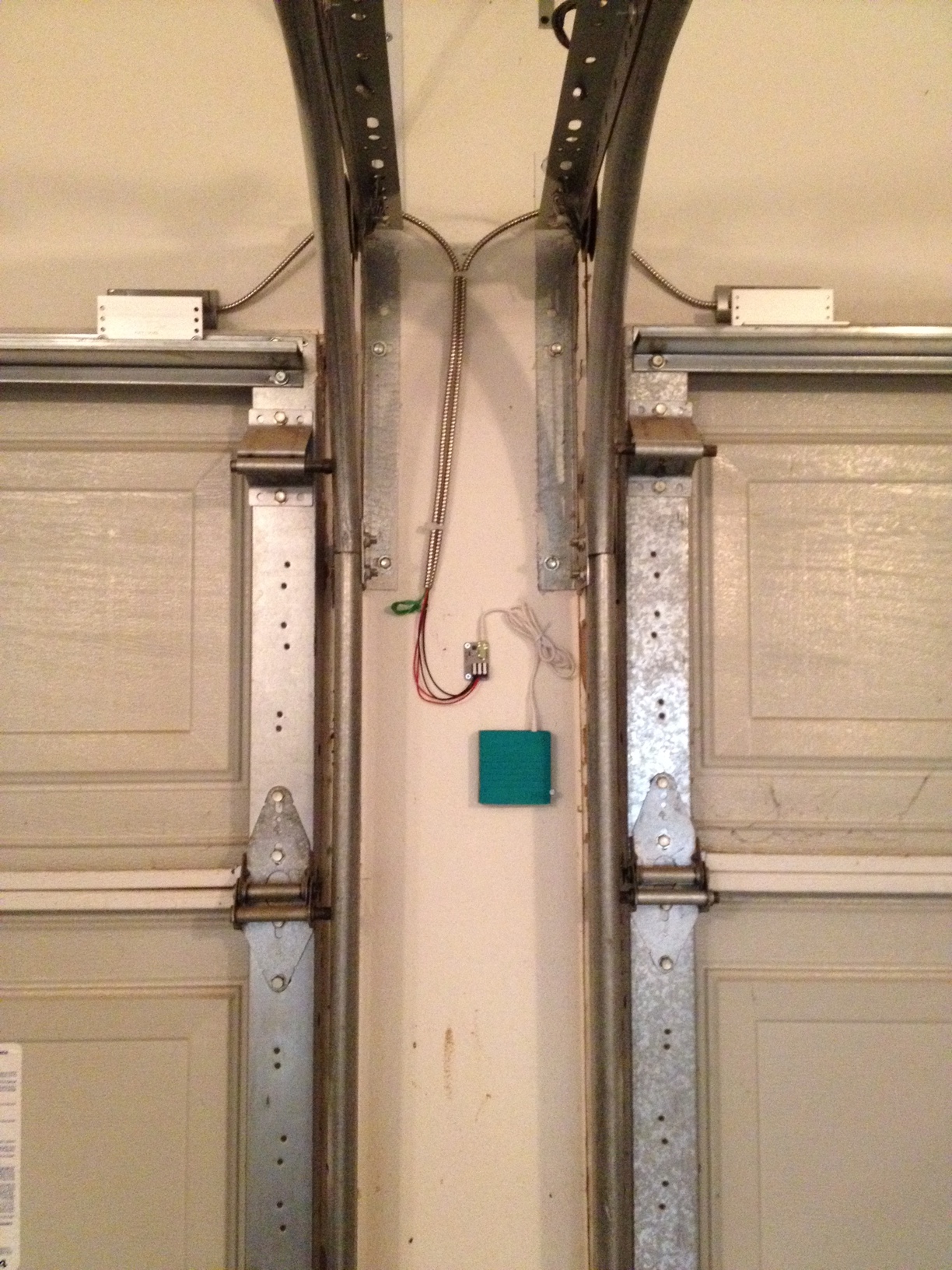
Install the sensor directly to the wall or floor and route the wires such that they will not interfere with the garage door as it travels up/down. Install the magnet and adjustable plate directly to the garage door so that the magnet is within a couple of inches of the sensor when the garage door is fully shut. I have two garage doors that I want to monitor so I installed a duplicate sensor on the adjacent garage door. (see photo)
;)
;)
Route the wires to the location where you want to install the Twine. You may need to use nylon cable ties to hold the wires in position to prevent getting in the way of the garage door travel. I installed mine in a location where I could easily access the Twine for battery replacement or maintenance. You may also want to consider a location that can easily access a power outlet so the Twine can be powered locally and not rely on battery power.
;)
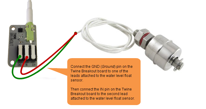
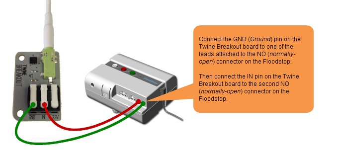
I used a 4D finish nail to hang the Twine on and a 6D common nail on the right-hand side of the Twine to hold it in place. The Twine breakout sensor board is also required and should be installed along with the Twine using the provided 1/8" stereo wire. The magnetic sensors can be wired directly to the Twine breakout board or you can extend them with additional wire if you need to install the Twine in a location that is a further distance than the existing sensor wires can reach. The black wires (common) from the sensors should be attached to the GND pin on the Twine breakout board. The red wires (NC) from the sensors should be attached to the IN pin on the Twine breakout board. The green wires (NO) from the sensors are not used in this project. Both garage doors are attached to the single Twine so that both doors can be monitored. Note, they are not monitored individually or discretely, but rather as one.
;)
;)
The last step is to use a micro-USB power supply to power the Twine locally. This will then use the mains power to power the Twine and the batteries will only be used for backup in the event of a power failure.
;)
;)
Configuring Twine
If you have not previously performed the initial setup configuration on your Twine, then please visit this article and perform the configuration steps before continuing.
Open a web browser and login to the Twine management web application:
https://twine.supermechanical.com/
Next, select the specific Twine device that you are working with from the drop-down menu at the top of the screen.
;)
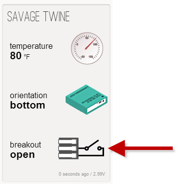
Next, we are going to create a new RULE to issue notifications when the Twine's breakout sensor is in the closed position for at least 15 minutes indicating that one of the the garage doors is open. (If you have any existing rules defined, you may want to delete them first.) Use the Add Rule button to create a new rule.
The new rule should be applied as follows:
WHEN
> "breakout" changes to "is closed" after "900" seconds
THEN
> send SMS text message (and/or email)
Also make sure to define the number of seconds for the trigger time and reset time under the "Options" section of the "When" trigger. I am using 900 seconds which is 15 minutes. So the garage door must be open for 15 minutes before triggering the notification.
Below is rule I am using:
;)
Testing
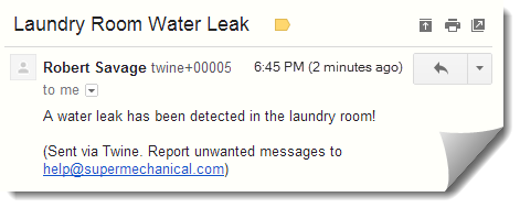
Now that we have installed the Twine and garage soor sensors to the garage doors and configured the logic rule, let's test the system. Simply open one of the garage doors and wait the configured delay time, fifteen minutes in my case, and you should receive the text notification (and/or email).
;)
;)
Final Thoughts
While this project was a little more complex and involved than the first Twine garage door project, I believe that this is truly a better approach for a permanent installation. Using this approach, the Twine can be powered locally and you can monitor multiple doors with a single Twine. Have fun automating your home with the Twine.
]]>
;)
;)
;)


;)
;)
;)
;)
;)

;)
;)
;)
;)
;)
;)
;)
;)
;)
;)
;)
;)
;)
;)
;)
;)
;)
;)
;)
;)
;)
;)
;)
;)
;)
;)
;)
;)
;)
;)
;)
;)
;)
;)
;)
;)
;)
;)
;)
;)
;)
;)
;)
;)
;)
;)
;)
;)
;)